GPS NTP with pfSense
Designing and making a GPS time reference for NTP on pfSense.
February 1, 2020
On Youtube I saw a video about a GPS time reference for networks. It used the same router OS called pfSense as me, so I could actually do this as well. This idea of a GPS time reference stuck with me and after some time I decided to actually make my own. Of course I wanted to make it look good and make it more professional compared to the one in the video.
So I got to work, in the summer of 2019 I started learning CAD software for PCB design. I first chose my main component, the MAX3232 from Texas Instruments. I chose this component as it is a widely known component for translating UART to RS-232 logic. After selecting my main component I used the datasheet of the MAX3232 to find out how to wire it up and replicated this onto my PCB.
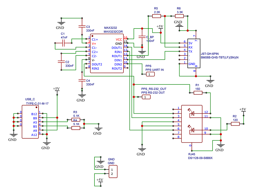
After selecting the compontents and putting them in the CAD program I wired it up as seen in Figure 1. As you see the MAX3232 chip is a central component on this board with a few resistors and capacitors to support its operation. The values were all calculated easily by hand or looked up in the datasheet of the MAX3232. I am using three connectors for data and power, I use a USB C connector for power while using an RJ-45 (8P8C) connector for carrying RS-232 lines. The JST-GH 6 pin connector is there to be able to plug in my GPS module without using an adapter cable as the module already uses this connector.

Click the picture to open the SVG version
The GPS module is called the DP0107 and contains the NEO-M8N GPS chip from U-blox, the GPS module itself is from a French company called Drotek. You can find the DP0107 module on their webstore. As said before the module has an UART in- and output on a JST connector, with the cable that comes with the module I can easily hook it up to my UART to RS-232 translation board and power the GPS module at the same time. There was one problem, the JST connector did not carry the PPS signal needed for my NTP reference. So I soldered a wire to the LED that was connected to the M8N's PPS output. This cable then connected to the translation board with a simple Dupont connector.
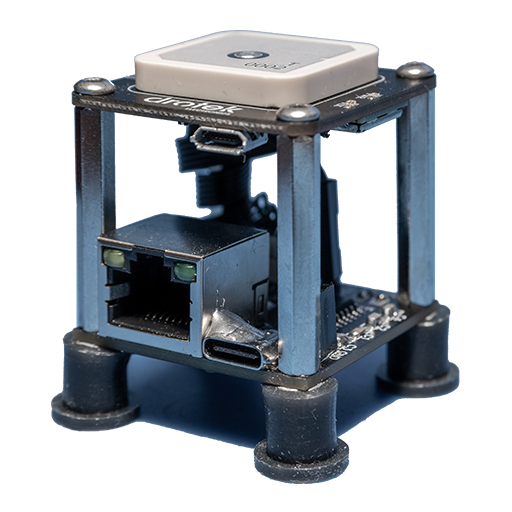
Assembling was done using metal standoffs, I got some fancy nickel plated ones to match the RJ-45 and USB C connectors. I plugged in the JST-GH cable and the PPS wire to the translation board and screwed the GPS board to the standoffs. The bottom rubber feet were reused from an old soldering iron that broke years ago. The end result can be seen in Figure 2. I put it on my desk near a window for good GPS reception and using a CAT6 cable for data and a simple USB2.0 USB C cable for power. Later I added an ugly blob of solder on the USB C connector to secure it better, since while using the device showed it was a structural weak point. If I knew this from the start I would have probably selected a better USB C connector, at least this one was dirt cheap.

If you would like to recreate the project, you can use the Gerber files for the translation board (see button below). You can see which components I used in Figure 1, The part numbers are in the subtitles for the important components. The resistors and capacitors are all sized 0805, the values of these components can also be found in Figure 1. You can copy the text in Figure 1 here using the SVG version with selectable text.